![]()
|
|
||||||||||||||||||||
|
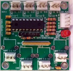
Industrial Quad RC Servo Motor Driver & Potentiometers Control Interface Board Module is an Original Manufacturing Engineering (OEM) industrial and commercial rated high performance, high efficiency board that utilizes potentiometers (POT) to control and drive both, RC Servos, direction, and angle.
The Quad RC Servo Motors Driver & Control Interface Board Module power of 4 to 6VDC. An additional power input allows injection of higher voltage to RC SERVO i.e. 7.4VDC, 12VDC etc.
The Quad RC-Servo Motor Driver & Control Interface Board Module produces the required PWM multiplexing signals at 50 Hz of PWM main frequency (period of 20ms) for controlling the RC Servo motors. The PWM signal is used for controlling the motors positions or directions. The positions and directions are direct result of the potentiometers (POTs, Pots) positions. The driver designed to support both, Industrial high quality RC Servo motors that require 2000 levels corresponding to 0-5VDC POT’s position and/or 255 levels standard of low quality RC Servo motors.
Please be advised that the exact PWM width is depending on the servo motor types and brands. Let our OEM engineer’s custom “tailor” the Servo Motor Driver to meet your application requirements and needs.
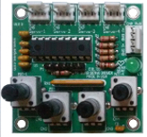
Two basic models are available - a built-in potentiometers and remote potentiometers (external POT) via wires and conveniently front mounted locking connectors.
The board also contains indication LED for Power On (PWR ON) and Microcontroller Self Testing (MST). The LED will blink "like HEART BEAT" once every second, indicating all of the board functions are running and powered correctly.
Shown above left, adjustments via quad turn potentiometers (POT) and on the right control remotely via external wired potentiometers.
The board offers the features needed for professional setting Radio Control (RC) servo motors position as a direct function of potentiometer movement.
Mounting is easy via four 0.156" mounting holes using 6-32 screws and wire (optional) via convenient conventional industrial standards locking connectors.
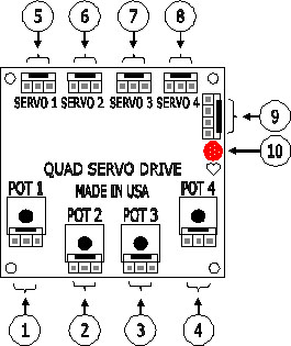
Quad RC Servo Motor Driver & Control Interface Board Module basic connections illustration
1. First channel, main on board potentiometer (POT-1) model A or external of board via locking type connector model B. Where; pins are marked (front left to right) GND, potentiometer Center-tap (C-1), +V
2. Second channel, main on board potentiometer (POT-2) model A or external of board via locking type connector model B. Where; pins are marked (front left to right) GND, potentiometer Center-tap (C-1), +V
3. Third channel, main on board potentiometer (POT-3) model A or external of board via locking type connector model B. Where; pins are marked (front left to right) GND, potentiometer Center-tap (C-1), +V
4. Forth channel, main on board potentiometer (POT-4) model A or external of board via locking type connector model B. Where; pins are marked (front left to right) GND, potentiometer Center-tap (C-1), +V
5. First channel external RC-Servo locking type connector. Where; pins are marked (front left to right) GND, +V, Signal (S-1)
6. Second channel external RC-Servo locking type connector. Where; pins are marked (front left to right) GND, +V, Signal (S-2)
7. Second channel external RC-Servo locking type connector. Where; pins are marked (front left to right) GND, +V, Signal (S-3)
8. Second channel external RC-Servo locking type connector. Where; pins are marked (front left to right) GND, +XV, Signal (S-4)
9. External Power connections via locking type connector. Where; pins are marked (front top to bottom) VX+, GND, +V, GND.
10. Heart-Beat LED indication. In-circuit debugger/programmer:
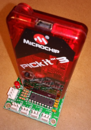
The Quad RC Servo Driver board comes (shipped) pre-loaded with software. Whoever, we can custom the code/software (C or Assembler) to fit your OEM needs. It done easily via Microchip's PICkit-2 or PICkit-3 USB type Programmer/Debugger.
Shown above PIC-KIT-3 USB programmer (optional) via dedicated on board 6 pins connector.
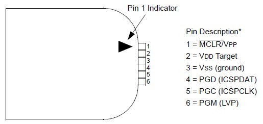
Connecting the PICkit3 to the RC Servo Driver board through standard ICSP interface using 6-pin on board connector. The programmer connector pin-out is shown in the figure below:
Please note the debugger
system can be configured to use standard
ICSP communication
for both programming and debugging functions. This PICkit-3
6-pin connection is the same one used by the older PICkit-2
Development Programmer/Debugger.
* The Microchip name and logo.
the Microchip, PIC, PICKIt 2, PICKIt 3 are register
trademark of Microchip Technology Inc.
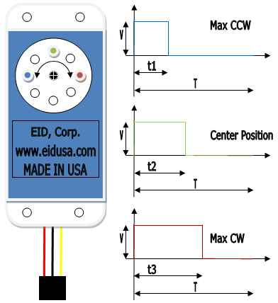
Illustration: RC Servo basic operation
Shown above RC Servo Motor basic operation illustration
Where;
T= 20.000mSec, t1= 1.000mSec, t2= 1.500mSec & t2= 2.000mSec, V = 4.8V to 24VDC (RC servo motor depended) & 3 wires: Red = Power, Black = Ground & Yellow = RC servo PWM signal.
Standard Features:
● Provides motors with smooth movement
● Linear Adjustable via POTs
● High efficiency circuitry
● Conveniently front mounted connections
● Conveniently front mounted LED for both power on and Microcontroller Self Testing (MST) indicators.
Board Dimensions:
Board width, length, height: 2.00" * 2.00" * 1.00"
Board Mouthing Dimensions:
Four (4) mounting holes (.156" Dia.) 1.70" * 1.70" on center.
Note: Use four (4) 6-32 screws and stand-offs to mount the board.
Caution: Do not mount the board where ambient temperature is outside the range of -10° C (15° F) to 45° (115° F). -20°C to +50°C (-4°F to 122°F).
Specifications:
|
||||||||||||||||||||
|
||||||||||||||||||||
|
|
||||||||||||||||||||